This application note explains the basic elements of LVDS signaling, details measurements based on an example standard and provides insight into oscilloscope-based test automation software which delivers faster and more consistent measurements.
The instruments referred to in this application note include the 5 Series MSO, 6 Series MSO and MSO/DPO70000C Series oscilloscopes, equipped with TekExpress LVDS test automation and advanced jitter analysis packages.
What is Low Voltage Differential Signaling (LVDS)?
Low Voltage Differential Signaling (LVDS) is a popular signaling system for applications requiring high speed data transfers using low power. High immunity to external disturbances is achieved by using differential conductors positioned very close to one another. Disturbances effect both traces equally (common mode) and are ignored by the receiver, which operates in differential mode. LVDS is also designed for low EMI. The two traces carry signals of opposite polarity, thus resulting in cancelling magnetic fields.
LVDS provides the foundation for multiple standards used in applications including LCD panels and graphics controllers, video interfaces, analog-to-digital converters (ADCs), and sensor systems. Several video standards rely on LVDS including OpenLDI, GVIF, GMSL, V-by-One1, and FPD-Link. Each one uses a physical layer based on LVDS with different protocols running on the physical layer.
Electrical Characteristics
LVDS signals use differential voltage swing on inverting and non-inverting lines in opposite directions, riding on a common mode voltage. The common mode (CM) voltage can vary from 0 V on up, and the peak-to-peak swing can be up to 400 to 600 mV.
Although LVDS is incorporated in multiple standards, most implementations rely on a differential termination of 100 Ω with a specified tolerance. In addition to point-to-point, there are also multipoint standards such as Bus LVDS and M-LVDS.
Video standards which use LVDS, such as OpenLDI, GVIF, GMSL, V-by-One, and FPD-Link have physical layers based on LVDS but the standards differ in clocking (embedded clock, explicit clock, spread-spectrum clocks) and lane specifications. LVDS is also used in signal converters such as ADCs and DACs.
The number of lanes in any of the aforementioned applications can vary from one to many. Video standards generally use multiple lanes and one or more clocks. In any multi-lane application, it is critical to control the skew between lanes.
Video Frame Basics
Since LVDS is often used to transfer video information, it may be helpful to review the structure of a video frame. The basic unit of a video frame is the pixel and the frame is an array of pixels. Each pixel contains red, green and blue (RGB) color information. On video buses, pixels are sent as sequences of bits in packets. For the receiver to understand the content of a frame, delineators are used to define the start of frame, start of row, etc. Much of the terminology comes from the days of analog composite video signals. A vertical synch signal (VSYNC) occurs once in every frame and it indicates the beginning of every new frame, as well as the end of previous frame. A horizontal synch (HSYNC) delineator occurs every time a new row of pixels starts. The frame includes vertical and horizontal blanking, which are delays between frames and rows, respectively. These are referred to as the front porch (HFP/VFP) which occurs prior to active video, and the back porch (HBP/VBP) which occurs after active video.
OpenLDI Example
To better understand a practical application of LVDS, let us look at a popular video standard, OpenLDI. This standard, with its electrical specifications based on TIA-644, is often used between graphics processors and LCD displays. Common display resolutions supported by OpenLDI v0.95 are as given in Table 1.
| Resolution | Common Name |
| 640x480 | VGA |
| 500x600 | SVGA |
| 1024x768 | XGA |
| 1280x1024 | SXGA |
| 1600x1024 | SXGAW |
| 1600x1200 | UXGA |
| 1920x1080 | HDTV |
| 1920x1200 | UXGAW |
| 2048x1536 | QXGA |
TABLE 1. Display resolutions supported by OpenLDI. Reference: OpenLDI Specification V0.95 Table 5-1.
The video signal is transferred in a frame as outlined in “Video Frame Basics” above. Frames are transferred over 3 to 8 data lanes with one or two clocks. OpenLDI has multiple variants:
- 18-bit single pixel, with each pixel represented by three 6-bit values for RGB
- 24-bit single pixel, with each pixel represented by four 8-bit values for RGB
- 18-bit dual pixel, with two pixels represented by a pair of three 6-bit values
- 24-bit dual pixel, with two pixels represented as a pair of four 8-bit values
Note that in the case of dual pixel implementations, two pixels are sent at the same time.
For each of the encoding schemes above, the physical layer takes on a different structure. Refer to Figure 1. The 18-bit single pixel format uses one clock and 3 lanes (A): A0 to A2 data lanes and CLK1. The dual pixel format uses the same lanes and clock, but adds another clock and 3 more lanes (B): A4 to A6 and CLK2.
The 24-bit single pixel format uses one clock and 4 lanes (A): A0 to A3 with CLK. The dual pixel format adds four more lanes and has two clocks and 8 lanes (B): A4 to A7 with CLK2 are used in addition to 24-bit single pixel lanes.
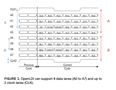
FIGURE 1. OpenLDI can support 8 data lanes (A0 to A7) and up to 2 clock lanes (CLK).
| Bits | Pixel Format | Data Lanes | CLK | Oscilloscope Channels* |
| 18 | Single | 3 | 1 | 4 |
| 18 | Dual | 6 | 2 | 8 |
| 24 | Single | 4 | 1 | 5 |
| 24 | Dual | 8 | 2 | 10 |
*Differential Probing
TABLE 2. OpenLDI variants with oscilloscopes or switch matrix channels needed for testing.
To test the Tx of the display controller, we would require an oscilloscope with a minimum of 4 channels and up to 10 channels depending on the number of bits per pixel and pixel mode chosen. One of the options to test beyond 4 channels is to use a switch matrix to test the channels in sequence. Another option is to use an 8 channel oscilloscope, like a 5 Series MSO with up to 8 channels. This configuration can test up to 8 lanes at once, saving significant time especially when performing characterization runs. The 5 Series MSO also offers long record length and a 12-bit ADC for accurate measurements.
The physical layer and electrical specifications of OpenLDI are based on TIA-644. The TIA-644 standard states that driver output transition times be less than 30% of the unit interval with a lower limit of 260 ps and 1 ns, respectively. This translates to scopes with bandwidth higher than 350 MHz. The LVDS transition times are defined for 20% to 80% of Vpp of the signal.
In OpenLDI, one bit-width is 1/7th of the pixel clock, which is 160 MHz. Thus, the data rate is seven times the clock rate, resulting in a max rate of 1.12 Gbps.
Some of the important measurements for OpenLDI verification include pre-emphasis, intra-pair skew, and inter-pair skew. The specifications in this section are per V0.95 of OpenLDI.
Pre-Emphasis: OpenLDI V0.95 supports video transmission over distances up to 10 m. The signal at the receiver end should be recoverable and hence, the signal is given a pre-emphasis. The pre-emphasis should be as per the OpenLDI V0.95 template shown in Figure 2.
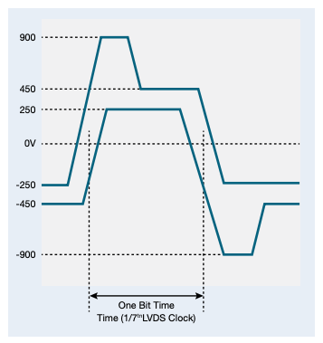
FIGURE 2. Tolerance masks for OpenLDI signals show allowable bit time and pre-emphasis.
Intra-pair Skew: This is the maximum permissible skew between the differential pair. The receiver should be able to tolerate skews up to 300 ps.
Inter-pair Skew Measurements: The skew between any two pairs of data lanes should not be more than 1 ns.
Some Key Measurements for LVDS
Testing various parameters of a video signal and especially, intra-pair and inter-pair skew over multiple channels calls for very accurate and reliable measurements. Given that displays are an integral part of automotive and industrial systems, characterization of the interface requires an automated tool that can run measurements over multiple process, voltage and temperature corners, as these systems operate in harsh environments.
Different video standards have different requirements. Some of the other key test requirements include applying equalizers of 1 GHz bandwidth.
The example of OpenLDI using LVDS illustrates several key measurements that are important in LVDS systems. Additional measurements may be required by other standards, or may be valuable for troubleshooting:
- Intra-pair skew: measures the skew within all differential pairs
- Inter-pair skew: measures the skew among all pairs
- Differential output voltage magnitude
- Output offset voltage (common mode)
- Unit interval
- Data width
- Clock frequency/period
- Transition Time: Rise Time (tᵣ)*. Fall Time (t𝒻)*. *tᵣ and t𝒻 are measured at 20% to 80% of the signal.
Jitter testing and analysis may be needed to measure jitter on both data signals and clocks. In some cases, clocks may use spread-spectrum modulation to control EMI. This adds some additional test complexity.
Many measurements may be required, however most of them can be automated with LVDS measurement packages and advanced jitter analysis packages available on Tektronix oscilloscopes.
Automated Measurements and TekExpress
The TekExpress software automates measurements associated with most variants of LVDS. It runs on 5 and 6 Series MSOs and MSO/DPO70000C oscilloscopes. Variants include bus standards associated with the LVDS physical layer as well as the physical layer of several popular video standards. TekExpress automation software is fully configurable. Test execution can be fully controlled using SCPI commands to further automate and customize the system.
The software can test offline waveforms, in pre-recorded mode, to facilitate multiple test runs.
The test setup consists of:
- Oscilloscope
– Advanced Jitter option
– TekExpress LVDS measurement automation option - Probes or phase-matched SMA cables
- DUT
Figure 3 shows setup diagrams for both phase-matched SMA-based connections and differential probes.
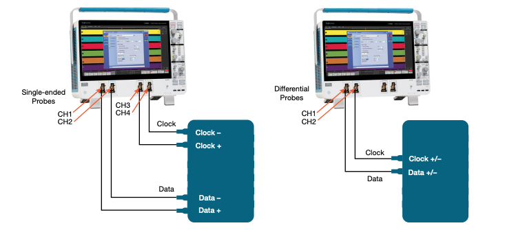
FIGURE 3. Measurements may be made using single-ended, matched SMA cables, or differential probes. Differential probes use fewer oscilloscope channels.
The TekExpress interface guides you through the process of setting parameters, choosing tests, and applying limits. Limits are configurable and may be saved for reuse. The application allows for multi-lane testing, up to 8 lanes with a 5 Series MSO and 4 lanes with a 6 Series MSO or MSO/DPO70000C.
The tests in the application are grouped under Data and Clock. Clock tests may be performed with or without spread-spectrum clocking (SSC). Data tests are organized into two subcategories: generic and jitter tests (Figure 4).
For greater testing speed and versatility, the testing package provides automatic mask generation, re-configurable clock/data recovery, pre-emphasis testing and up to 2 filter files to support equalization.
For systems with embedded clocks, the application provides fully-configurable clock and data recovery. (Figure 5) Multiple clock recovery methods are supported including constant clock, PLL custom bandwidth (Type 1/Type 2) and explicit clock. (The “explicit clock” is applicable in cases where a separate clock is available.)
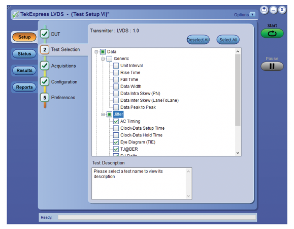
FIGURE 4. TekExpress automation software follows a logical flow from test setup to reporting. There are two groups of tests from which to choose: data and clock.
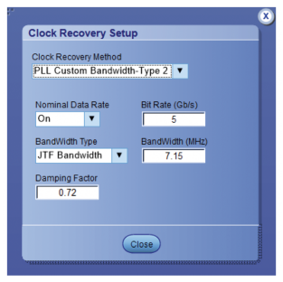
FIGURE 5. Clocks can be recovered from the signal using constant clock and PLL techniques. A separate clock may also be used if available.
Automask generates a mask based on the signals’ maximum swing voltage, data rate and mask shape. The auto-generated mask can be further fine-tuned manually. The mask shape can be chosen from among hexagon, octagon and square shapes. Once generated, the mask is used with the eye diagram to check for violations and provide a pass/fail report.

FIGURE 6. The test automation software generates an eye pattern mask which can be adjusted manually.
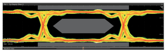
FIGURE 7. The mask is used to identify violations during testing.
After measurements have been completed, the automation software generates a test report. For each parameter it gives the associated lane number, measured value, pass/fail indication, and margin. Captured screen images may also be included. Results can be sorted by test name, lane number and result (pass/fail). Reports may be saved in PDF, mht and csv formats.
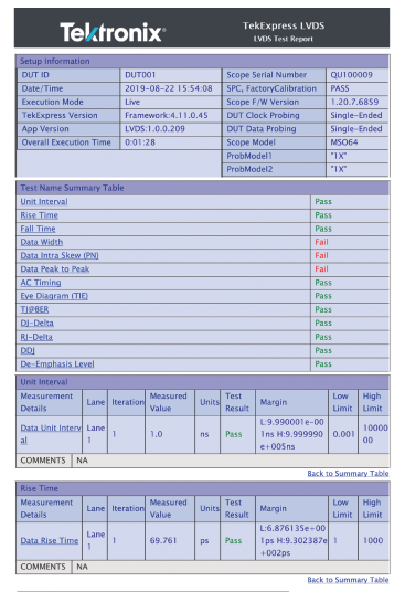
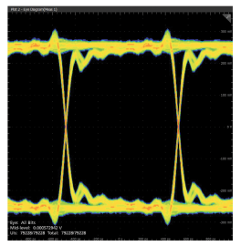
FIGURE 8. Once measurements have been completed, a report can be automatically generated incorporating pass/fail results, measurement values, and margins.
Conclusion
Low voltage differential signaling provides the basis for several communications standards, many of which are used in harsh environments. This, coupled with multi-lane implementations, makes testing both important and complex. Test automation software running on an oscilloscope can provide faster and more consistent measurements.